Long Answer Questions - 5 Marks
Que 1. Briefly explain an activity to plot the magnetic field lines around a bar magnet. Sketch the field pattern for the same specifying field directions.
A region A has magnetic field lines relatively closer than another region B. Which region has stronger magnetic field. Give reason to support your answer.
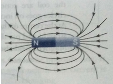
Ans. 1. Take a drawing sheet and fix it on a smooth table with adhesive tape.
2. Place a bar magnet in the middle of the drawing sheet and draw its boundary with a sharp pencil.
3. Place a magnetic compass near one end of the magnet (N-pole) and mark the positions of the two ends (N and S-poles) of the compass needle using a sharp pencil.
4. Shift the compass from this position and place it in such a way that S-pole of its needle is on the point you marked in previous step for N-pole.
5. Again mark the position of the other end (N-pole) of the compass needle.
6. Repeat the steps 4 and 5, till you reach the other end (S-pole) of the bar magnet.
7. Join all the points with a sharp pencil to get a smooth curve.
8. Put the compass at some other points near the N-pole of the magnet and draw another magnetic field lines. Similarly, draw many field lines on both the sides of the bar magnet as shown in figure.
9. Observe the pattern of the magnetic field lines.
Result: Magnetic field lines can be drawn around a bar magnet using a magnetic compass.
The field lines do not cross each other.
Region A has stronger magnetic field. This is due to the strength of the field is proportional to the relative closeness of field lines.
Que 2. Briefly explain an activity to plot the magnetic field lines around a straight current carrying conductor. Sketch the field pattern for the same, specifying current and field directions. What happens to the field,
(a) if the strength of the current is decreased?
(b) if the direction of the current is reversed?
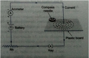
Ans. The pattern of magnetic field lines around a straight conductor carrying current can be described by the following activity.
(i) Insert vertically a long straight wire carrying an electric current so that it passes through the centre of a horizontal piece of plastic board as shown in figure.
(ii) Take care that the plastic board is fixed and does not move up and down. Now, sprinkle some iron filings onto the plastic board to show the shape of the field.
(iii) You will notice that the iron filings get arranged round the wires in the shape of circles. This is due to the reason that the magnetic field lines around the current carrying straight conductor are circular The iron filings align along these field lines.
(iv) On reversing the direction of flow of current, we observe that the iron filing arrange themselves in circles around the wire showing that the magnetic field lines are still circular in nature.The direction of the magnetic field can be obtained by using a compass. If the current direction is reversed, the direction of the magnetic field is also reversed.
(a) When current through the wire is decreased, field also gets reduced.
(b) When the current is reversed, field also gets reversed in direction.
Que 3. (a) With the help of a labelled diagram, explain the distribution of magnetic field due to a current through a circular loop. Why is it that if a current carrying coil has turns the field produced at any point is n times as large as that produced by a single turn?
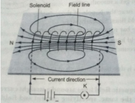
(b) Draw a pattern of magnetic field formed around a current carrying solenoid. What happens to the magnetic field when the current through the solenoid is reversed?
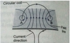
Ans. (a) The pattern of the magnetic field lines near the wires of the coil are concentric circles. The diameter of these circles goes on increasing as we move away from the wire. At the centre of the circular loop, the field lines are nearly straight and parallel.
(b) Magnetic field also gets reversed.
Que 4. (a) Explain an activity to show that a current-carrying conductor experiences a force when placed in a magnetic field field.
(b) State the rule which gives the direction of force acting on the conductor..
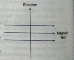
(c) An electron moves perpendicular to a magnetic field as shown in the figure.
What would be the direction of force experienced on the electron?
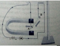
Ans. (a) A small aluminium rod suspended horizontally from a stand using two connecting wires. Place a strong horseshoe magnet in such a way that the rod lies between the two poles with the magnetic field directed upwards. For this, put the north pole of the magnet vertically below and south pole vertically above the aluminium rod. Connect the aluminium rod in series with a battery, a key and a rheostat. Pass a current through the aluminium rod from one end to other (B to A). The rod is displaced towards left. When the direction of current flowing through the rod is reversed, the displacement of rod across towards right.
(b) Fleming’s left- hand rule.
Stretch the thumb, forefinger and middle finger of your left hand such that they are mutually perpendicular to one another. If the forefinger points in the direction of magnetic field and the middle finger in the direction of current, then the thumb will points in the direction of motion or the force acting on the conductor.
(c) According to Fleming's left hand rule, the direction of force is perpendicular to the direction of magnetic field and current. We know that the direction of current is taken opposite to the direction of motion of electrons. Therefore, the force is directed upwards from the plane of the paper.
Que 5. With the help of a diagram, describe an experiment to show that a change in current flowing through a coil induces an electric current in a neighbouring coil.
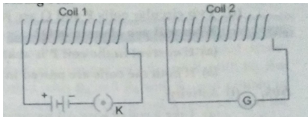
Ans. Take two different coils of insulated copper wire having large number of turns (50 or even more). Insert the coils over a non-conducting cylindrical thick paper roll as shown in figure. Connect a battery of 6V, a plug key K in series of coil-1. With coil-2. connect a sensitive galvanometer. Now put the plug in key K. Galvanometer joined with coil-2 also gives a momentary deflection and then pointer quickly returns to its mean position. On removing plug from key K in coil-1 the needle momentarily moves, but to the opposite side. It means that now the current flows in the opposite direction in coil 2. So we conclude that current is produced in coil-2 whenever the current flowing in the neighoring coil is changing.
Que 6. Draw an appropriate schematic diagram showing common domestic circuits and discuss the importance of fuse. Why is it that a burnt out fuse should be replaced by another fuse of identical rating?
Ans.
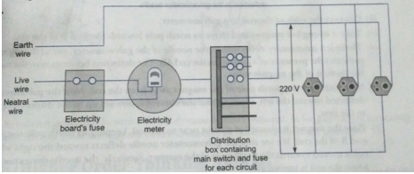
A fuse in a circuit prevents damage to the appliances and the circuit due to overloading. Otherwise, the appliances or the circuit may be damaged.
When current in the circuit exceeds the value of fuse rating, the fuse wire burns due to overloading. This causes a gap in the circuit and the current stops flowing in the circuit.
This is done due to the reason so that the circuit or the appliances to be connected in the circuit continue functioning without any damage in future.
Que 7. (i) Two circular coils P and Q are kept close to each other, of which coil P carries a current. If coil P is moved towards Q, will some current be induced in coil Q? Give reason for your answer and name the phenomenon involved.
(ii) What happens if coil P is moved away from Q?
(iii) State any two methods of inducing current in a coil.
Ans. (i) When coil P is moved towards Q, current will be induced in coil Q. This is because on moving P the magnetic field associated with Q increases and so a current is induced. The Phenomenon is electromagnetic induction.
(ii) If P is moved away from Q, the field associated with Q will decrease and a current will be induced but in the opposite direction
(iii) Current can be induced in a coil by (a) moving a magnet towards or away from the coil (b) moving a coil towards or away from a magnet (c) rotating a coil within a magnetic field.
Que 8. (i) With the help of an activity, explain the method of inducing electric current in a coil with a moving magnet. State the rule used to find the direction of electric current thus generated in the coil.
(ii) Two circular coils P and Q are kept close to each other, of which coil P carries a current. What will you observe in Q?
(a) If current in the coil P is changed?
(b) If both the coils are moved in the same direction with the same speed? Give reason.
Ans. (i) Activity:
(a) Take a coil of wire AB having a large number of turns.
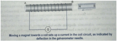
(b) Connect the ends of the coil to a galvanometer.
(c) Take a strong bar magnet and move its north pole towards the end B of the coil.
(d) There is a momentary deflection in the needle of the galvanometer, say to the right. This indicates the presence of a current in the coil AB. The deflection becomes zero the moment the motion of the magnet stops.
(e) Now withdraw the north pole of the magnet away from the coil. Now the galvanometer is deflected toward the left, showing that the current is now set up in the direction opposite to the first.
(f) Place the magnet stationary at a point near to the coil, keeping its north pole towards the end B of the coil. We see that the galvanometer needle deflects toward the right when the coil is moved towards the north pole of the magnet. Similarly, the needle moves toward left when the coil is moved away.
When the coil is kept stationary with respect to the magnet, the deflection of the galvanometer drops to zero.
To find the direction of electric current Fleming's right hand rule is applied. According to it, if we stretch the forefinger, middle finger and thumb of our right hand mutually perpendicular in such a way that thumb points along the direction of motion of conductor, forefinger along the direction of magnetic field; then the middle finger points along the direction of induced current.
(ii) (a) When current in P is changed, the field associated with Q will vary causing an induced current in Q.
(b) If both the coils are moved in the same direction with same speed, there will not be any change in the field associated with Q. Hence no current will be induced in Q.
Que 9. Explain the underlying principle and working of direct current generator (or DC dynamo) by drawing a labelled diagram.
Ans. A device used to convert mechanical energy into electrical energy is called an electric generator. An armature-coil rotating in a magnetic field develops an alternating emf and sends alternating current in an external circuit. If, however, the connections of the ends of the coil to the external circuit are interchanged every time the emf in the coil reverses, the current in the external circuit
flows always in the same direction. This is the principle of a DC dynamo.
The working of a single-coil DC dynamo is shown in the figure. The ends of the armature-coil ABCD are connected to the two separated segments R1 of a single copper ring R, which is called the 'split-ring commutator'. RI and R2 rotate along with the armature between two brushes B1 and B2 to which the external circuit is connected.
When the armature-coil ABCD is rotated clockwise (say), an emf is induced in the coil and a current flows in the direction ABCD (Fleming's right-hand rule), as shown in Fig (a). In the external circuit, the current flows from B1 to B2. For half the revolution, R1 is in contact with B1 and R2 with B2. But as soon as the coil passes the vertical, R1 comes in contact with B2 and R2 with Bi and remain so during the next half revolution [Fig. (b)]. Although the induced emf in the coil is reversed and the current in the coil flows in the direction DCBA, but in the external circuit the current still flows from B1 to B2.
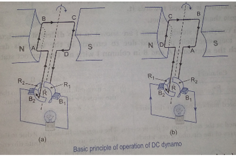
The current generated by such a simple dynamo is uni-directional. As long as the coil is rotating, the direct current flows through the device connected to the terminals of the generator.

